Kia Optima: Suspension System
Service data
| Service Data |
Front Suspension
|
Item |
Specification |
|
Suspension type |
Macpherson Strut |
|
Shock absorber type |
Gas |
Rear Suspension
|
Item |
Specification |
|
Suspension type |
Multi link |
|
Shock absorber type |
Gas |
Wheel & Tire
|
Item |
Specification |
|
|
Steel wheel |
6.5J * 16 |
|
|
Aluminum wheel |
6.5J * 16 |
|
|
7.0J * 17 |
||
|
7.5J * 18 |
||
|
Tire |
205/65 R16 |
|
|
215/60 R16 |
||
|
215/55 R17 |
||
|
235/45 R18 |
||
|
T125/80 D16 |
||
|
T135/80 D17 |
||
|
Tire Pressure |
205/65 R16 |
2.50 kg/cm2 (35psi) |
|
215/60 R16 |
||
|
215/55 R17 |
||
|
235/45 R18 |
||
|
T125/80 D16 |
4.50 kg/cm2 (60psi) |
|
|
T135/80 D17 |
||
Wheel Alignment
|
Item |
Specification |
|
|
Front |
Rear |
|
|
Toe-in (Total) |
0.12°±0.2° |
0.17°±0.2° |
|
Toe-in (Individual) |
0.06°±0.1° |
0.085°±0.1° |
|
Camber angle |
-0.5°±0.5° |
-1.0°±0.5° |
|
Caster angle |
5.0°±0.5° |
- |
|
King-pin angle |
14.5°±0.5° |
- |
Tightening torque
| Tightening Torque |
Front Suspension
|
Item |
N·m |
kgf·m |
lb·ft |
|
Tire wheel hub nut |
107.9 - 127.5 |
11.0 - 13.0 |
79.6 - 94.0 |
|
Front strut upper mounting nuts |
53.9 - 73.5 |
5.5 - 7.5 |
39.8 - 54.2 |
|
Brake hose bracket bolt |
8.8 - 13.7 |
0.9 - 1.4 |
6.5 - 10.1 |
|
Stabilizer bar link to strut assembly |
98.1 - 117.7 |
10.0 - 12.0 |
72.3 - 86.8 |
|
Strut assembly to knuckle |
196.1 - 215.7 |
20.0 - 22.0 |
144.7 - 159.1 |
|
Strut assembly self locking nut |
107.9 - 117.7 |
11.0 - 12.0 |
79.6 - 86.8 |
|
Lower arm to sub frame |
156.9 - 176.5 |
16.0 - 18.0 |
115.7 - 130.2 |
|
Stabilizer bar to stabilizer bar link |
98.1 - 117.7 |
10.0 - 12.0 |
72.3 - 86.8 |
|
Stabilizer bar bracket mounting bolts |
49.0 - 63.7 |
5.0 - 6.5 |
36.2 - 47.0 |
|
Universal joint to pinion of steering gear |
49.0 - 58.8 |
5.0 - 6.0 |
36.2 - 43.4 |
|
Roll rod bracket to sub frame |
49.0 - 63.7 |
5.0 - 6.5 |
36.2 - 47.0 |
|
Roll rod bracket to body |
107.9 - 127.5 |
11.0 - 13.0 |
79.6 - 94.0 |
|
Sub frame staybolts |
44.1 - 58.8 |
4.5 - 6.0 |
32.5 - 43.4 |
|
Sub frame mounting bolt and nut |
176.5 - 196.1 |
18.0 - 20.0 |
130.2 - 144.7 |
|
Steering ger box heat protector bolts |
7.8 - 11.7 |
0.8 - 1.2 |
5.7 - 8.6 |
|
Steering gear box to sub frame |
107.9 - 127.5 |
11.0 - 13.0 |
79.6 - 94.0 |
|
Sub frame to dynamic damper |
44.1 - 53.9 |
4.5 - 5.5 |
32.5 - 39.8 |
Rear Suspension
|
Item |
N·m |
kgf·m |
lb·ft |
|
Tire wheel hub nut |
107.9 - 127.5 |
11.0 - 13.0 |
79.6 - 94.0 |
|
Shock absorber to body |
49.0 - 63.7 |
5.0 - 6.5 |
36.2 - 47.0 |
|
Shock absorber to lower arm |
137.3 - 156.9 |
14.0 -16.0 |
101.3 - 115.7 |
|
Rear shock absorber lock nut |
19.6 - 24.5 |
2.0 - 2.5 |
14.4 - 18.0 |
|
Lower arm to knuckle |
137.3 - 156.9 |
14.0 -16.0 |
101.3 - 115.7 |
|
Stabilizer link to lower arm |
58.8 - 68.6 |
6.0 - 7.0 |
43.4 - 50.6 |
|
Upper arm to knuckle |
137.3 - 156.9 |
14.0 -16.0 |
101.3 - 115.7 |
|
Lower arm to sub frame |
107.8 - 117.6 |
11.0 - 12.0 |
79.5 - 86.8 |
|
Assist arm to sub frame |
107.8 - 117.6 |
11.0 - 12.0 |
79.5 - 86.8 |
|
Assist arm to knuckle |
137.3 - 156.9 |
14.0 - 16.0 |
101.3 - 115.7 |
|
Trailing arm to knuckle |
98.1 - 117.7 |
10.0 - 12.0 |
72.3 - 86.8 |
|
Wheel spped sensor bracket bolts |
8.8 - 13.7 |
0.9 - 1.4 |
6.5 - 10.1 |
|
Trailing arm to body |
117.7 - 137.3 |
12.0 - 14.0 |
86.8 - 101.3 |
|
Stabilizer bar to sub frame |
44.1 - 53.9 |
4.5 - 5.5 |
32.5 - 39.8 |
|
Body to sub frame mounting bolts and nuts |
176.5 - 196.1 |
18.0 - 20.0 |
130.2 - 144.7 |
|
Rear sub frame steering |
44.1 - 58.8 |
4.5 - 6.0 |
32.5 - 43.4 |
Special service tools
| Special Service Tools |
|
Tool Name / Number |
Illustration |
Description |
|
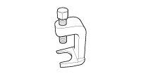
Ball joint puller 09568-2J100 |
|
Use for removal of ball joint |
|
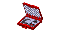
Lower arm ball joint remover 0K545-A9100 |
|
Used for removal of front lower arm ball joint |
|
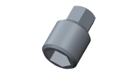
Front strut lock nut removal tool 0K546-F6100 |
|
Used for removal and installation of front strut lock nut |
|
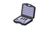
Shock absorber lock nut removal tool 09546-3X100 |
|
Used for removal and installation the rear shock absorber lock nut |
Troubleshooting
| Troubleshooting |
|
Symptom |
Expected cause |
Countermeasure |
|
Heavy weight feeling on steering wheel |
Faulty on front wheel alignment |
Adjust or repair |
|
Over rotation resistance of lower arm ball joint |
Replace |
|
|
Over rotation resistance of strut bearing |
Replace |
|
|
Too low amount of Tire air pressure |
Adjust |
|
|
Steering wheel recovery trouble |
Faulty on front wheel alignment |
Adjust or repair |
|
Noise or ride comfort trouble |
Faulty on wheel alignment |
Adjust or repair |
|
Inappropriated tire air pressure |
Adjust |
|
|
Faulty function of shock absorber |
Replace |
|
|
Damaged coil spring |
Replace |
|
|
Damaged stabilizer |
Replace |
|
|
Damaged lower arm bushing |
Replace |
|
|
Stabilizer link fixing nut got loosen |
Retighten |
|
|
Damaged stabilizer link (dust cover tearing, ring broke away) |
Replace |
|
|
Abnormal worned out of tire |
Faulty wheel alignment |
Adjust or repair |
|
Inappropriated tire air pressure |
Adjust |
|
|
Unstable steering wheel |
Front wheel alignment trouble |
Adjust or repair |
|
Lower arm ball joint turning resistance is too small |
Replace |
|
|
Damaged lower arm bushing |
Replace |
|
|
Vehicle pushed aside phenomenon |
Wheel alignment trouble |
Adjust or repair |
|
Unbalance of right/left tire |
Adjust or replace |
|
|
Damaged or transformed lower arm bushing |
Replace |
|
|
Damaged coil spring |
Replace |
|
|
Steering wheel juddering |
Front wheel alignment trouble |
Adjust or repair |
|
Wheel balance trouble |
Adjust or repair |
|
|
Lower are ball joint turning resistance is too much or too small |
Replace |
|
|
Damaged stabilizer |
Replace |
|
|
Damaged lower arm bushing |
Replace |
|
|
Shock absorber operating trouble |
Replace |
|
|
Coil spring trouble |
Replace |
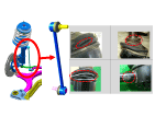
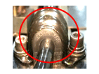
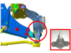
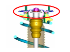
Strange sound type from under body by parts
|
Conditions for occurrence |
Strange sound on uneven ground |
|||
|
Parts |
Step bar link |
Step bar bushing |
Lower arm ball joint |
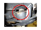
Strut insulator |
|
Trouble area |
|
|
|
|
|
Type of strange sound |
Rattling, Creaking noise |
Squeaking noise |
Clunking, Knocking noise |
Clicking, Creaking noise |
|
Occurring area |
Under part |
Under part |
Under part |
Upper part |
|
Driving speed |
20 - 40 ㎞/h (12.4 - 24.9 m/h) |
While low speed driving (20 - 40 ㎞/h (12.4 - 24.9 m/h)) |
20 - 40 ㎞/h (12.4 - 24.9 m/h) |
- |
|
Condition of road |
Uneven road / bump |
Uneven road / bump |
Uneven road / bump |
Uneven road / tough road |
|
Reason |
Loosen / leakage (teared down) / corrosion |
Separation of bar and bushing / slip |
Loosen / leakage (teared down) / corrosion |
Tightened (decrease torque) and interference |
|
Conditions for occurrence |
Strange sound while going through uneven road / tough road |
|||
|
Parts |
Strut / Shock absorber |
Strut / Shock absorber |
Strut / Shock absorber |
Strut / Shock absorber |
|
Trouble area |
|
|
|
|
|
Type of strange sound |
Rubbing noise |
Clicking, Creaking noise |
Rubbing noise |
Clicking noise |
|
Occurring area |
Upper part |
Upper part |
Upper part (rear) |
Upper part (rear) |
|
Driving speed |
15 - 25 ㎞/h (9.3 - 15.5 m/h) |
15 - 25 ㎞/h (9.3 - 15.5 m/h) |
15 - 40 ㎞/h (9.3 - 24.9 m/h) |
30 - 50 ㎞/h (18.6 - 31.1 m/h) |
|
Condition of road |
Uneven road |
Uneven road |
Uneven road and tough road |
Tough road |
|
Reason |
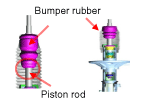
Friction sound from piston load and bumper rubber inner side |
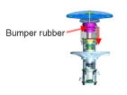
Rolled down bumper rubber (tapping sound of bumper rubber upper part and insulator under part) |
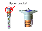
Adhesion trouble of upper bracket rubber |
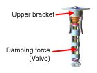
Suspension tuning trouble (damping force, rubber characteristic) |
|
Conditions for occurrence |
Strange sound on uneven road |
Strange sound while steering |
Strange sound while driving |
|
|
Parts |
Lower arm "G" bushing |
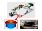
Cross member bushing |
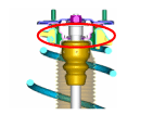
Strut bearing |
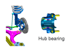
Wheel / Hub bearing |
|
Trouble area |
|
|
|
|
|
Type of strange sound |
Rubbing noise |
Clicking noise |
Clicking noise |
Roaring noise |
|
Occurring area |
Under part |
Under part |
Upper part |
Lower and side part |
|
Driving speed |
10 - 40 ㎞/h (6.2 - 24.9 m/h) |
- |
- |
20 - 60 ㎞/h (12.4 - 37.3 m/h) |
|
Condition of road |
Bump / tough road |
Even road |
Even road |
Even road |
|
Reason |
Dropped off / fallen off |
Dropped off / fallen off |
Grease leakage |
Damaged from outer impact, foreign substance inflow |
Wheel and tire diagnosis
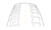
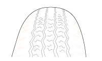
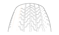
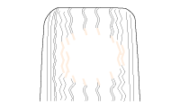
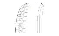
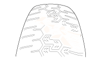
Wheel /tire noise, vibration and harshness concerns are directly related to vehicle speed and are not generally affected by acceleration, coasting or deceleration. Also, out-of-balance wheel and tires can vibrate at more than one speed. A vibration that is affected by the engine rpm, or is eliminated by placing the transmission in Neutral is not related to the tire and wheel. As a general rule, tire and wheel vibrations felt in the steering wheel are related to the front tire and wheel assemblies. Vibrations felt in the seat or floor are related to the rear tire and wheel assemblies. This can initially isolate a concern to the front or rear.
Careful attention must be paid to the tire and wheels. There are several symptoms that can be caused by damaged or worn tire and wheel. Perform a careful visual inspection of the tires and wheel assemblies. Spin the tires slowly and watch for signs of lateral or radial runout. Refer to the tire wear chart to determine the tire wear conditions and actions
|
Wheel and tire diagnosis |
||||||||||||||||||||||||||
|
Rapid wear at the center |
Rapid wear at both shoulders |
Wear at one shoulder |
||||||||||||||||||||||||
|
|
|
|
||||||||||||||||||||||||
|
|
|
||||||||||||||||||||||||
|
Partial wear |
Feathered edge |
Wear pattern |
||||||||||||||||||||||||
|
|
|
|
||||||||||||||||||||||||
|
|
|
||||||||||||||||||||||||
- Front Suspension System
- Rear Suspension System
- Rear Shock Absorber
- Rear Coil Spring
- Rear Upper Arm
- Rear Lower Arm
- Rear Assist Armature
- Trailing Arm
- Rear Stabilizer Bar
- Rear sub frame
- Tires/Wheels
- Tire Pressure Monitoring System
 Joint Assembly (Wheel side)
Components and components location
Components
1. Wheel side joint assembly
2. Wheel side circlip
3. Wheel side boot band
4. Wheel side boott
5. Shaft ...
 Front Suspension System
Components and components location
Components
1. Strut complete
2. Roll rod bracket
3. Sub frame
4. Stabilizer bar
5. Steering gear box
6. Dynamic da ...
Other information:
Kia Optima DL3 2019-2025 Service and Repair Manual: Panorama Sunroof Switch
Schematic diagrams Connector and Terminal Function Repair procedures Inspection 1. Remove the overhead console lamp. (Refer to Lighting System - "Overhead Console Lamp") 2. Check for continuity between the terminals ...
Kia Optima DL3 2019-2025 Owner's Manual: Before driving
Before entering vehicle Be sure that all windows, outside mirror(s), and outside lights are clean. Check the condition of the tires. Check under the vehicle for any sign of leaks. Be sure there are no obstacles behind you if you intend to back up. Necessary inspections Fluid levels, su ...

