Kia Optima: Tire Pressure Monitoring System / TPMS Receiver
Description and operation
| Description |
TPMS Receiver : IBU (Integrated Body Control Unit) integrated management
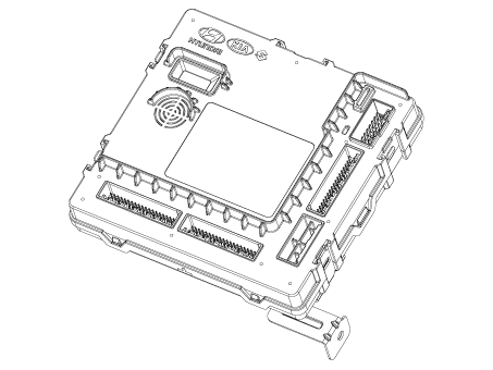
| 1. |
Mode
|
| 2. |
Overview
|
| Operation |
| 1. |
General Function
|
| 2. |
General Conditions to Learn New Sensors :
|
| 3. |
General Conditions to Un-Learn a sensor that is removed :
|
Repair procedures
| Removal |
| 1. |
Remove the Integrated Body Control Unit (IBU). (Refer to Body Electrical System - "Integrated Body Control Unit (IBU)") |
| Installation |
| 1. |
Install in the reverse order of removal. |
| Diagnosis With KDS |
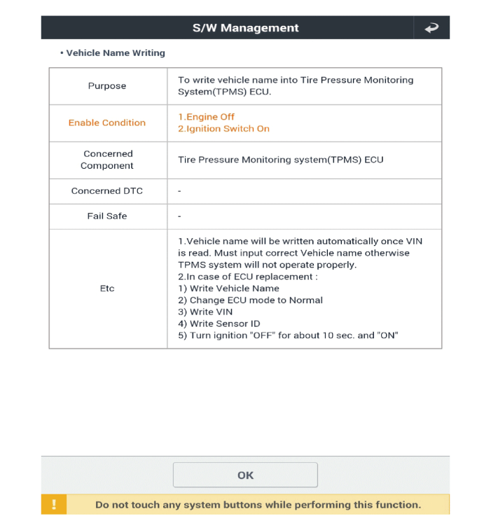
Vehicle Name Writing
The main contents of diagnostic method using diagnostic device are as follows:
| 1. |
Connect self-diagnosis connector (16 pins) located in the lower driver side crash pad to self-diagnostic device, and then turn on the self-diagnostic device after key is ON. |
| 2. |
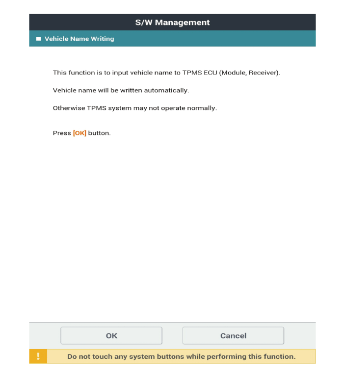
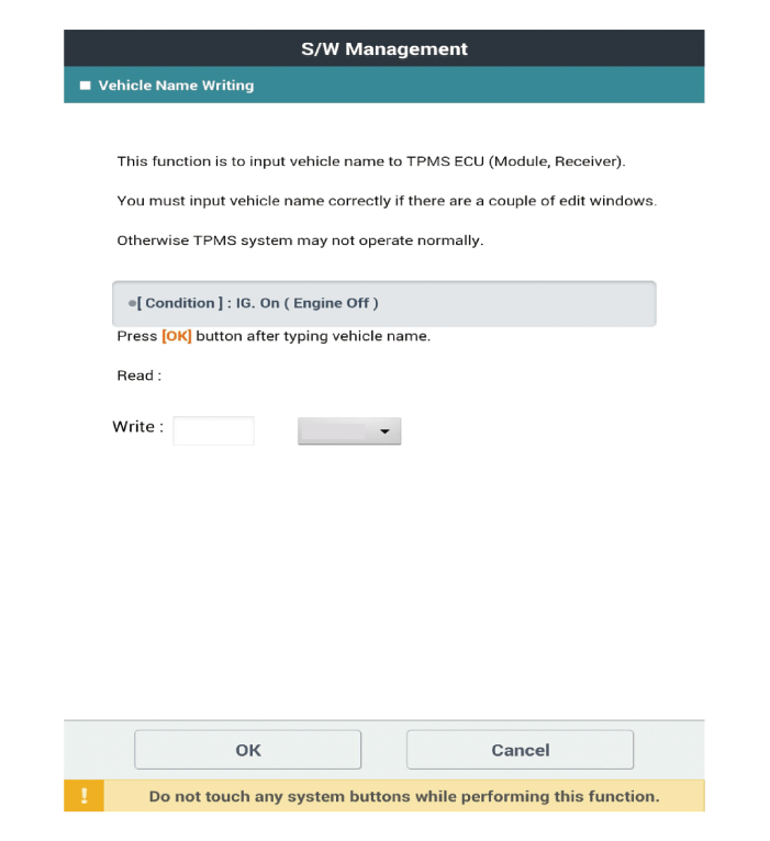
Select the "IBU-TPMS" and "Vehicle Name Writing" on KDS vehicle selection screen, then select OK.
The vehicle naming (Read/Write) is automatically typed and just select the vehicle's option in the selection tab below. ※ The vehicle naming code is different as the vehicle models
|
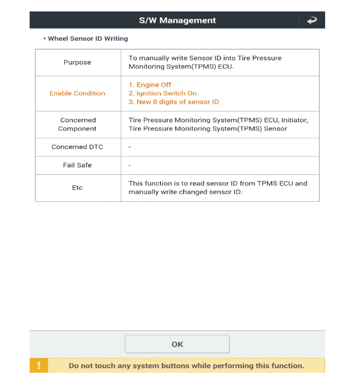
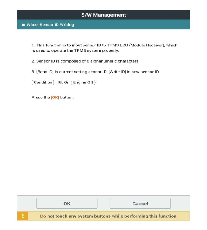
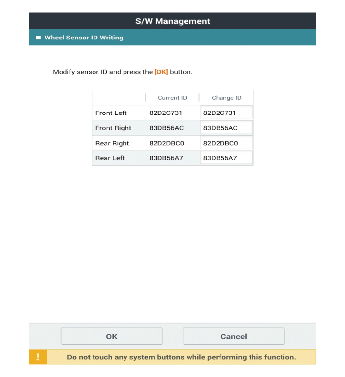
Wheel Sensor ID Writing
The main contents of diagnostic method using diagnostic device are as follows:
| 1. |
Connect self-diagnosis connector (16 pins) located in the lower driver side crash pad to self-diagnostic device, and then turn on the self-diagnostic device after key is ON. |
| 2. |
Select the "IBU-TPMS" and "Wheel Sensor ID Writing" on KDS vehicle selection screen, then select OK.
|
 TPMS Sensor
Description and operation
Description
1.
Function
•
By detecting the pressure, temperature, acceleration, and battery
condition, tra ...
 Steering System
Service data
Service Data
Item
Specification
Type
Electric Power Steering System
Steering gear
Type
...
Other information:
Kia Optima DL3 2019-2025 Owner's Manual: Steering wheel
Electric power steering (EPS) The power steering uses an electric motor to assist you in steering the vehicle. If the engine is off or if the power steering system becomes inoperative, the vehicle may still be steered, but it will require increased steering effort. The electric power steering ...
Kia Optima DL3 2019-2025 Owner's Manual: Engine oil
Checking the engine oil level ■ THETA 2.4L - GDI 1. Be sure the vehicle is on level ground. 2. Start the engine and allow it to reach normal operating temperature. 3. Turn the engine off and wait for a few minutes (about 5 minutes) for the oil to return to the oil pan. 4. Pull the dipstic ...

