Kia Optima DL3: Cooling System / Radiator
Components and components location
| Components |
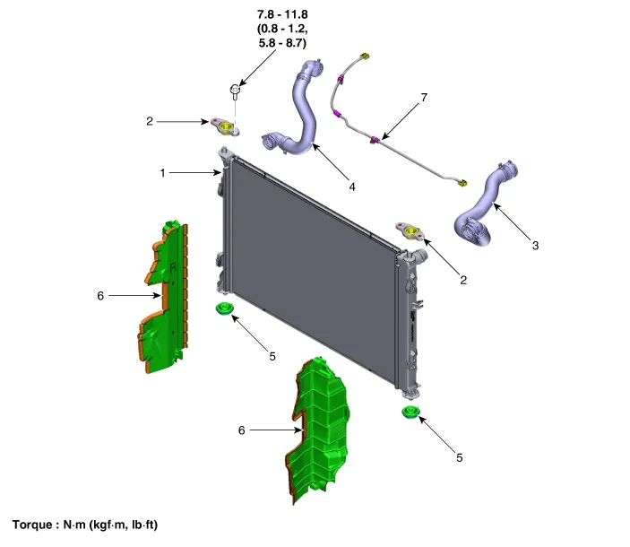
| 1. Radiator 2. Radiator upper mounting bracket 3. Radiator upper hose 4. Radiator lower hose |
5. Radiator lower mounting insulator
6. Radiator air guard 7. Degassing hose and pipe |
Repair procedures
| Removal and Installation |
| 1. |
Remove the cooling fan. (Refer to Cooling System - "Cooling Fan") |
| 2. |
Drain engine coolant by loosening the drain plug. (Refer to Cooling System - "Coolant") |
| 3. |
Disconnect the radiator upper hose (A).
|

| 4. |
Disconnect the radiator lower hose (A).
|

| 5. |
Remove the front bumper assembly. (Refer to Body (Interior and Exterior) - "Front Bumper Assembly") |
| 6. |
Remove the radiator upper mounting bolts (A) and then remove the radiator upper mounting brackets.
[LH]
[RH]
|


| 7. |
Remove the radiator air guard (A). [LH]
[RH]
|


| 8. |
Separate the condenser from the radiator. |
| 9. |
Pull the raditor (A) upward and remove it from engine room.
|

| 10. |
Install in the reverse order of removal. |
| 11. |
Fill with engine coolant. (Refer to Cooling System - "Coolant") |
| 12. |
Start engine and check for leaks. |
| 13. |
Recheck engine coolant level. |
| Inspection |
Reservoir Cap Testing
| 1. |
Install the pressure cap and pressure tester on a SST (0K253-G5100).
|

| 2. |
Apply a pressure of 125.52 - 154.94 kpa (1.28 - 1.58 kg/cm², 18.21 - 22.47 psi). |
| 3. |
Check for a drop in pressure. |
| 4. |
If the pressure drops, replace the cap. |
Radiator Leakage Test
| 1. |
Wait until engine is cool, then carefully remove the reservoir tank cap and fill the radiator with engine coolant, then install it on the pressure tester.
|

| 2. |
Apply a pressure tester to the radiator and apply a pressure of 125.52 - 154.94 kpa (1.28 - 1.58 kg/cm², 18.21 - 22.47 psi). |
| 3. |
Inspect for engine coolant leaks and a drop in pressure. |
| 4. |
Remove the tester and reinstall the reservoir tank cap.
|

Components and components location Components 1. Cooling fan 2. Cooling fan motor 3. Cooling fan shroud Specifications Specifications Item Specification Fan type PULLER Fan speed control Resisor Air flow rate (㎥/h) 1,950 - 8% min.
Components and components location Components 1. Water temperature control assembly 2. Engine coolant temperature sensor 3.
Other information:
Kia Optima DL3 2019-2026 Service and Repair Manual: Power Seat Motor
Components and components location Components 1. Lumbar support motor 2. Reclining motor 3. Front height motor 4. Rear height motor 5. Slide motor Repair procedures Inspection 1.
Kia Optima DL3 2019-2026 Service and Repair Manual: Washer Switch
R
Categories
- Manuals Home
- Kia Optima Owners Manual
- Kia Optima Service Manual
- Motor Driven Power Steering
- External Amp
- Cooling System
- New on site
- Most important about car
