Kia Optima DL3: Brake System / Brake Pedal
Components and components location
| Components |
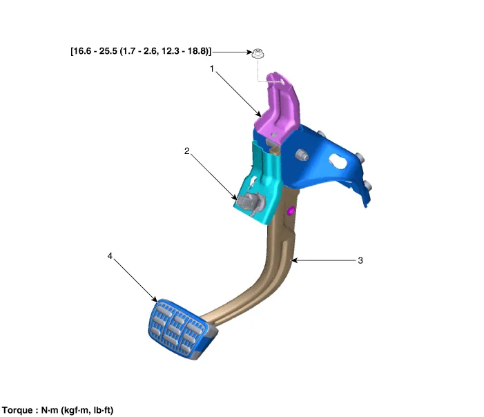
| 1. Brake member assembly 2. Stop lamp switch |
3. Brake pedal arm assembly
4. Brake pedal pad |
Repair procedures
| Removal |
| 1. |
Turn ignition switch OFF and disconnect the negative (-) battery cable. |
| 2. |
Remove the crash pad lower panel. (Refer to Body - "Crash Pad Lower Panel") |
| 3. |
Remove the drive airbag module. (Refer to Restraint - "Drive Airbag Module") |
| 4. |
Disconnect the stop lamp switch connector (A).
|

| 5. |
Separate the snap pin (A) and clevis pin (B).
|

| 6. |
Loosen the nuts (A), (B) and then remove the brake pedal assembly.
|


| Inspection |
| 1. |
Check the brake pedal for bending or twisting. |
| 2. |
Check the brake pedal return spring for damage. |
| 3. |
Check the stop lamp switch. (Refer to Brake System - "Stop Lamp Switch") |
| Installation |
| 1. |
Install in the reverse order of removal.
|

Components and components location Components 1. HECU flare nuts. 2. HECU to body mounting nuts. 3. Master cylinder to HECU flare nut.
Components and components location Components 1. Brake member assembly 2. Stop lamp switch 3. Brake pedal arm assembly 4.
Other information:
Kia Optima DL3 2019-2026 Service and Repair Manual: Receiver-Drier
Repair procedures Replacement 1. Remove the condenser. 2. Remove the cap (A) on the bottom of the condenser with a L wrench. Tightening torque : 9.81 - 14.71 N.
Kia Optima DL3 2019-2026 Service and Repair Manual: Evaporator Temperature Sensor
Description and operation Description The evaporator temperature sensor will detect the evaporator core temperature and interrupt compressor relay power in order to prevent evaporator from freezing by excessive cooling. The evaporator temperature sensor has the Negative Temperature Coefficient (NTC).
Categories
- Manuals Home
- Kia Optima Owners Manual
- Kia Optima Service Manual
- Brake System
- Automatic Transaxle System
- Motor Driven Power Steering
- New on site
- Most important about car
